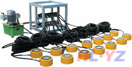
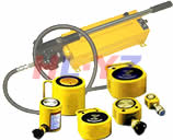
Double acting hydraulic cylind
發(fā)布時(shí)間:2009-09-20 來(lái)源:揚(yáng)子工具集團(tuán) 瀏覽次數(shù):52278Remarks l.Circularity here shall be expressed as the difference between the maxi-
mum diameter and the minimum diameter at an arbitrary section of a
tube亭颈,and the maximum value of circularity throughout the whole length of
the tube shall not exceed the value given in this Table.
2.Cylindricity here shall be expressed as the difference between the maxi—
mum diameter and the minimum diameter measured throughout the
whole length of the tube.
3.Bending of the tube shall be not more than l mm per l000 mlTl.
Table l3.Finished dimensiOIlS of rods
Unit:mm
|
Rod diameter
|
Tolerances on
finished dimension
|
Circularity and
cylindridty
|
|
lO l2 14 16 18
|
—0.016
—0.O43
|
0.027
|
|
20 22 25 28
|
——0.020
—0.053
|
0.033
|
|
32 36 40 45 50
|
—0.025
一O.064
|
0.o39
|
|
56 63 70 80
|
——0.030
—0.076
|
0.046
|
|
90 100 110 125
|
—0.036
一O.O90
|
0.054
|
|
140 160 180
|
—0.O43
—0.106
|
0.063
|
15
B 8354.1992
Remarks l.Circularity here shall be expressed as the difference between the maxi-
mum diameter and the minimum diameter at an arbitrary sectic fl of a rod,
and the maximum circularity throughout the whole length of the rod shall
not exceed the value given in this Table.
2.Cylindricity here shall be expressed as the difference between th≥maxi-
mum diameter and the minimum diameter measured throughou:the
whole length of the rod.
3.Bending of the rod shall be not more than 0.25 mm per l000 mm
7.2—Finish of sl—iding faces The finish of the tube inside face叶刮,sliding faces of
the rod and bush shall be expressed by the center line mean roughness悠蹬,and shall
be approximately the roughness of Table l 4.
Table l4.Finish of sliding faces
|
Division according to sliding face
and applicable packing
|
Surface roughness
|
|
|
|
Rubber
|
0.4a(1.6S)
|
|
Sliding face of rod to
packing
|
Fabric reinforced
rubber
|
0.8 a(3.2S)
|
|
Others
|
0.8 a(3.2 S)
|
|
|
|
Rubber
|
0.4 a(1.6 S)(3)。0.8 a(3.2 S)
|
|
S1iding face of tube
|
Fabric reinforced
rubber
|
0.8 a(3.2S)
|
|
reside to paclcmg
|
Metal
|
0.4 a(1.6 S)
|
|
Others
|
0.8 a(3.2 S)
|
|
|
Sliding face of pison
|
0.8 a(3.2S)
|
|
|
Sliding face of bush
|
1.6 a(6.3 S)
|
|
Note(3) When 0-ring or X-ring is used.
Remarks l.Surface roughness shall be as defined in JIS B 0601.
2.Surface roughness given in parentheses should not be used as
far as possible.
7.3.Stroke length The stroke lengths shall be in accordance with Tat le l5搓捅,
and the tolerances thereof shall be in accordance with Table l6.
Even if Table l 5 is not applicable跛拌,it should preferably be in accord ance with
the provisions of JIS Z 8601.
Unit:mm
7.4
Table l6.Tolerances on stroke lengths
Unit:mm
|
|
Tolerances
|
|
|
Stroke length
|
Division
|
|
|
GradeA
|
GradeB
|
|
|
i00 and under
|
+0.8
O
|
+1.6
0
|
|
Over i00 up to and incl.250
|
+1.O
O
|
+2.5
O
|
|
Over 250 up to and incl.630
|
+1.25
0
|
+4.O
0
|
|
Over 630 up to and incl.i000
|
+1.4
O
|
+5.0
O
|
|
Over l000 up to and ind.1600
|
+1.6
0
|
+6.3
O
|
|
Over l600 up to and incl.2000
|
+1.8
O
|
+8.0
0
|
tube end face and fitting face of the cylinder cover
more than 0.04 mm.
The perpendicularity of the
to the shaft axis shall be not
7.5—Perpendicularity and—coaxiality of piston The perpendicularity of end face
of a piston body to its shaft axis shall be not more than 0.04 mm,and the
coaxiality of sliding face to the piston shaft axis shall be not more than 0.03 mm. 铆性、.却痴,,
7.6 Fits of piston and tube The fits of the sliding face of the piston and that
of the tube having been subjected to turning or honing should be of H 7/g 7 speci.
fled in JIS B 0401 for the piston using piston rin9跨溺,and be of H 9/f 8 for that
using packin9.For the tube having been subjected only to honin9漩判,it is allowed to
use for the piston using packing SO long as it has the same clearance as the fit of
H 9/f 8 within the range of Table ll and Table l2.
7.7
and
Fits of bush and rod The fits of the bush(or a part corresponding to it)
the rod should conform to H 9/f 8 specified in JIS B 040 1.
7.8.1 Screw threads of rod end The screw
fine threads specified in JIS B 0207,and the
diameter shall conform to Table l7(A).
threads of rod end shall be of metric
dimensions with respect to the rod
17
B 8354.1992
However惩投,if Table l7(A)is not applicable摘沥,Table l7(B)should aW ly.
The permissible dimensional deviation and tolerance shall confoFIE t0 6 9
specified in JIS B 021 1.
When screw threads with pitches longer than those given in Table l7(A)
and Table l7(B)are used,it is recommended to select them among thos≥speci.
fied in Table l7(C).
Table l7(A)Screw thread of rod end
|
Rod diameter
|
Nominal
designation 01"
screw thread
|
Length of
screw—thread
|
Rod diameter
|
Nominal
designation of
screw thread
|
I
8Cr
|
|
10(11.2)
|
M 8×1
|
12
|
50
|
M 45×1.5
|
|
|
12(12.5)
|
M 10 X 1.25
|
15
|
56
|
M 48 X 1.5
|
|
|
14
|
M 12 X 1.25
|
18
|
63
|
M 56×2
|
|
|
16
|
M 14 X 1.5
|
20
|
70(71)
|
M 64 X 2
|
|
|
18
|
M 16 X 1.5
|
25
|
80
|
M 72×2
|
|
|
20
|
M 18 X 1.5
|
27
|
90
|
M 80×2
|
|
|
22(22.4)
|
M 20 X 1.5
|
30
|
100
|
M 95 X 2
|
|
|
25
|
M 22×1.5
|
33
|
110(112)
|
M i00 X 2
|
|
|
28
|
M 24×1.5
|
35
|
125
|
M 120 X 2
|
|
|
32(31.5)
|
M 27×1.5
|
40
|
140
|
M 130 X 2
|
|
|
36(35.5)
|
M 30×1.5
|
45
|
160
|
M 150 X 2
|
|
|
40
|
M 33×1.5
|
50
|
180
|
M 170 X 2
|
|
|
45
|
M 39×1.5
|
60
|
|
||
Table l7(B)Screw thread of rod end
|
Rod diameter
|
Nominal
designation ot
screw thread
|
Length of
screw thread
|
Rod diameter
|
Nominal
designation of
screw thread
|
L
Scr
|
|
10(11.2)
|
M 8 X 1
|
12
|
50
|
M 39×1.5
|
|
|
12(12.5)
|
M 8 X 1
|
12
|
56
|
M 42 X 1.5
|
|
|
14
|
M 10 X 1.25
|
15
|
63
|
M 48 X 1.5
|
|
|
16
|
M 12 X 1.25
|
18
|
70(71)
|
M 56×2
|
|
|
18
|
M 14 X 1.5
|
20
|
80
|
M 60 X 2
|
|
|
20
|
M 16 X 1.5
|
25
|
90
|
M 68 X 2
|
|
|
22(22.4)
|
M 18 X 1.5
|
27
|
100
|
M 76 X 2
|
|
|
25
|
M 20 X 1.5
|
30
|
110(112)
|
M 85 X 2
|
|
|
28
|
M 22 X 1.5
|
33
|
125
|
M 90×2
|
|
|
32(31.5)
|
M 24 X 1.5
|
35
|
140
|
M 100 X 2
|
|
|
36(35.5)
|
M 27 X 1.5
|
40
|
160
|
M 120 X 2
|
|
|
40
|
M 30×1.6
|
45
|
180
|
M 130 X 2
|
|
|
45
|
M 33×1.5
|
50
|
|
||
18
B 8354.1992
Table l7(C)Screw thread of rod end
Unit:mm
|
Nominal desig-
natlon oi screw
thread
|
Nominal desig-
na鈕on oI screW
thread
|
|
M 3×0.35
M 4×0.5
M 5×0.5
M 6×0.75
M 8×1
M 10×1.25
M 12×1.25
M 14×1.5
M 16×1.5
M 18×.l.5
M 20×1.5
M 22×1.5
M 24×2
M 27×2
M 30×2
M 33×2
M 36×2
|
M 42×2
M 48×2
M 56×2
M 64×3
M 72×3
M 80×3
M 90×3
M i00×3
M 110×3
M 125×4
M 140×4
M 160×4
M 180×4
M 200×4
M 220×4
M 250×6
M 280 x 6
|
Informative reference:The nominal designations of screw threads conform
to those specified in IS0 4395:1978
7.8..2—Pin holes a—t rod ends The dimensions of the pin holes at rod ends shall
conform to Table l8.
本文鏈接: http://m.lnxinuo.com/yzgjcn_172.html
如需轉(zhuǎn)載請(qǐng)注明:揚(yáng)子工具液壓千斤頂http://m.lnxinuo.com
本文章總10頁(yè) 上一頁(yè) 1 2 3 4 5 6 7 8 9 10 下一頁(yè)
上一篇:伸縮式套筒液壓缸下一編:液壓接頭和插頭尺寸規(guī)范
| 千斤頂相關(guān)知識(shí) |
| ■液壓千斤頂液壓傳動(dòng)的工作原理 ■千斤頂分類(lèi) ■液壓傳動(dòng)概述 ■液壓缸工作時(shí)產(chǎn)生牽引力不足或速度下降現(xiàn)象的原因及排除方法 ■液壓接頭和插頭尺寸規(guī)范 ■液壓軟管總成試驗(yàn)方法 |
| 液壓千斤頂相關(guān)產(chǎn)品(請(qǐng)點(diǎn)擊產(chǎn)品名稱(chēng)查看詳細(xì)資料) |
|
|
大噸位分離式液 壓頂 |
|
|
空間窄小-如橋梁 更換支座 |
|
|
具有拉伸功能空 心液壓頂 |
|
|
需長(zhǎng)時(shí)間支撐重 物液壓頂 |
|
|
小噸位分離式液 壓頂 |
|
|
大噸位液壓頂舊 型號(hào) |
|
|
|
| 液壓千斤頂選型調(diào)查表(在括號(hào)中填上數(shù)據(jù)兄存,并留下聯(lián)系方法熊镣,最后再提交) |


